So the simulation of Movement 114 is only a little over half done, and I am thinking about what's next.
"designed to show a curious property of the epicyclic train. The Wheel, A, is fixed upon a stationary stud about which the arm, C,D, revolves. In this are are two pinions, M, N, upon which is fitted loosely a thick wheel, B, gearing with A, and upon the other are three loose wheels, E, F, G, all geared with B. When the arm, C, D, is turned round the the stud, motion is given to the three wheels, E, F, G, on their common axis, viz. the pin N; the three forming with the intermediate wheel, B, and the wheel, A, the distinct epicyclic trains. Suppose A to have twenty teeth, F twenty, E twenty-one, and G nineteen; as the arm, C, D, is turned around, F will appear not to turn on its axis, as any point in its circumference will always point in one direction, while E will appear to turn slowly in one and G in the other direction, which -an apparent paradox- gave rise to the name of the apparatus."
Still confused? Try here.
Wish me luck.
Wednesday, May 30, 2007
Monday, May 28, 2007
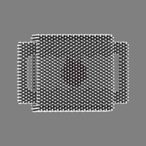
the finished Low Friction Carbon Nanotube Bearing... more or less
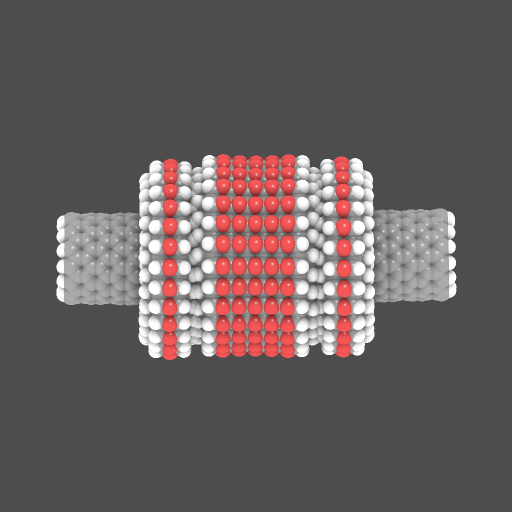
I finished the bearing tonight except mine looks a little pinched. I will have to extend the center tube slightly to ever use it, but that's no big deal. For tonight it looks like I am turning my back, slightly, on being a vastly patient professional. I am shamed.
Damian has posted a very interesting tutorial regarding this bearing on his blog. He says more, and in a better way, than I could. If you are interested in nanostructures, and since your reading this it is a safe bet you are, I recommend checking it out.
Also, basically for the hell of it, I sent an email to Toshiba regarding a sponsorship. The good news is they haven't said no yet.
The Movement 114 simulation should be completed in a couple days. Regardless of how it turns out, I plan on making a very pretty animation with QuteMol of it.
More to follow.
Sunday, May 27, 2007
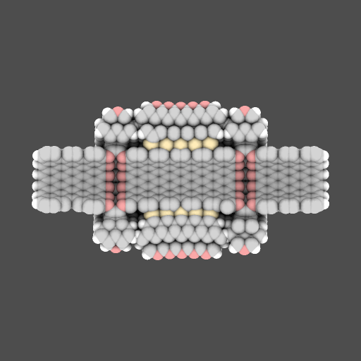
progress on the Low-Friction Carbon Nanotube Bearing Assembly

This was all I managed to complete tonight. I started off the same way, cutting a small piece from Damian's original ring and rebuilding it. I found out that in order for this to work perfectly I needed to deduce the original moiety or else my ring would not be the right size after I extruded it. In hindsight this is pretty obvious. Moiety is a term from chemistry I never encountered in my two semesters, but now I think of it as the unit cell of a crystalline lattice. In this case, the smallest repeating unit of the ring.
Since this ring needs to attach to a carbon nanotube of a specific size, I could tell right away when I was off on the fragment. It took a couple hours, and a serious case of wah-eye*, to find the right piece I needed to rebuild the ring. There was nothing too elegant in this, pretty much trial and error.
I also made the same mistake in the large ring I posted last night, making it way too large. I'll have to fix that too. Lessons learned and all.
Also, I still can't decide which format of picture I like best in QuteMol, so that is why I keep mixing up the graphics standards.
Movement 114 is crunching away on the other computer. I am not expecting anymore freeze ups. I remembered late last night that the other computer did the same thing once while playing Doom 3, so it is something idiosyncratic to that computer.
*wah-eye is a term left over from video games, short for watery eyes from intense monitor looking.
Saturday, May 26, 2007
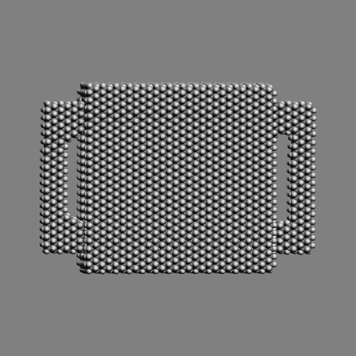
revisiting Damian's bearing
Well Damian was nice enough to send me everything I needed to see how his bearing was built, so that is what I have been up to tonight after restarting the Movement 114 simulation. I switched to the other computer too. The previous one (where it froze) was one I assembled myself. Coincidence?
I started with the center section which I carved into a tiny piece that was manageable and could be extruded. By extruded I mean the right hand side will, in essence (I am sure there are more technical ways to explain it), plug into the left hand side. This is a great feature in NE1 that allows you to make very long chains and rings of things very easily.

I next rebuilt this fragment one atom at a time. This took a little over an hour and a few tries because I would lose my place and had to nearly start over. But I eventually got it.

This was the hard part. After this fragment was completed, all I had to do was extrude it into a 16 piece ring and adjust it.

I will work on finishing the complete bearing tomorrow.
another freeze
The simulation froze up again. Bummer. I came home and heard that awful hissing sound; you actually have to unplug the computer to restart it. There is a simulator patch available. Hopefully it will address whatever is causing these freeze ups. I will install it and try again. And just in case anyone is thinking this is some ploy to get out of finishing Movement 114 with saving face, all "he knew it wouldn't work, tried to blame it on the program" and stuff. It's not. I will also try to run the simulation on another computer too, the one I ran the 151 hour cnt srg simulation on.
More to follow...
More to follow...
Friday, May 25, 2007
a couple more outtakes and simulation update
The simulation of Movement 114 is 30% complete after 52 hours. And in the spirit of the last post here are a couple other things that are not exactly frame worthy. The first is rather technical. If that's not your thing, scroll past it for something very embarrassing.
First an honest attempt at measuring the modulus of rigidity of a carbon nanotube. I had intended to post this to see if anyone knows why it went so horribly wrong.

I used this equation for the modulus of rigidity: G = (TL)/(Jθ)
Here T is torque = 500e-9 N-m
L is length of the tube = 24.51e-10 m
J is the polar moment of inertia. Here I used (π /32)[(d1-d2)^4]. d1-d2 would be the thickness of the tube. For this I looked up the covalent radius of carbon (77pm) and multiplied it by two to get the diameter of the carbon atom and subsequently the thickness of the tube.
θ is the amount of twist the torque accomplished. I used a jig to measure this and it came out to 12.3 degrees or 0.21 radians.
When you do this arithmetic you get a ridiculous answer, something like a billion-trillion Gpa.
Anybody see anything I didn't?
And before I decided to totally redesign Movement 114, in a moment of desperation, I was actually considering something like this:

Yes those are carbon nanotube halves bonded to the rack. I sure hope the new design works...
First an honest attempt at measuring the modulus of rigidity of a carbon nanotube. I had intended to post this to see if anyone knows why it went so horribly wrong.
I used this equation for the modulus of rigidity: G = (TL)/(Jθ)
Here T is torque = 500e-9 N-m
L is length of the tube = 24.51e-10 m
J is the polar moment of inertia. Here I used (π /32)[(d1-d2)^4]. d1-d2 would be the thickness of the tube. For this I looked up the covalent radius of carbon (77pm) and multiplied it by two to get the diameter of the carbon atom and subsequently the thickness of the tube.
θ is the amount of twist the torque accomplished. I used a jig to measure this and it came out to 12.3 degrees or 0.21 radians.
When you do this arithmetic you get a ridiculous answer, something like a billion-trillion Gpa.
Anybody see anything I didn't?
And before I decided to totally redesign Movement 114, in a moment of desperation, I was actually considering something like this:

Yes those are carbon nanotube halves bonded to the rack. I sure hope the new design works...
Wednesday, May 23, 2007
simulation update
I started the latest simulation of Movement 114 a couple of days ago, but I have ran into some problems. Two near instantaneous power outages and a freeze up (accompanied by an amazing hissing sound from the speakers) have forced me to restart the simulation three times. I can get a back up power supply, but I am not sure what cause the freeze. In the mean time I have been messing around and trying to recreate (loosely) Damian Allis' Low-Friction Carbon Nanotube Bearing Assembly. Mine is still kind of crappy...


Now the excuses:
1. I am using my trusty old Toshiba laptop (perhaps I should approach them regarding an endorsement deal for one of their top of the line models?) and things are painstakingly slow, forcing me to economize on the atom count.
2. I only have the two pictures to work from, and I am having trouble discerning exactly how it's built.
3. I still have a lot to learn and only spent a couple hours working on it.
I had not intended for you to see the wiggly thing on the right. I thought I deleted it, but I just hid it from view while working on other stuff. QuteMol shows all. I could have re-made the pictures without it but thought you deserved to see everything, kind of like how the American space program had a bunch of rockets blow up in full view of the media while the Russians had the benefit of failing in secrecy.
Also Damian's blog has not been accessible today, but if you haven't been there before, keep trying.
Sunday, May 20, 2007
a promising start to the new design
First it looks like my estimation for the simulation was way off, in a good way. This animation was compiled from a 1000 frame/100 steps per frame simulation, and it only took 14 hours. Not bad. The sluggishness I was experiencing during construction did not carry over to the simulation. I believe this makes since because building the part, lots of rotations and view changes, may have taxed my video card and ram, and the speed of the simulation would depend more on the processor. That's my theory anyway. For the record, at a half gig, my computer could stand an upgrade. Also I am using an ATI Radeon 9500 video card, so not top of the line there either.
Maybe my dreams of falling asleep in the penumbra of a processor farm will have to wait, but I am sure I will need it someday, all rack mounted, dozens of twinkling LEDs tapping out messages from the future in pseudo-morse, radiator fins on the roof blazing the IR spectrum like some techno-creature in heat. Yes, someday.
I know this simulation was way too short to see if this design will ultimately work, but for right now I just want to make sure nothing started flying off the thing. Nothing did. You can see that the pinion starts to twist the casing too. Next I will anchor the casing at the corners (just imagine this casing is bonded to some monolithic substrate) and run a long simulation.
More to follow.
Saturday, May 19, 2007
movement 114: new design with casing


I spent most of this evening building the casing. Again I am going with silicon carbide. I also spent a little time extending the pinion teeth by another row of carbon atoms and reshaping the pinion slightly to make it more symmetrical.
Right now I am mainly concerned with two things: the possibility that the rack will shear off hydrogen atoms on the inside of the casing and the monumental size of this new design. There are over 16,000 atoms making this part, and they're giving my pentium 4 all it wants and more. I can't yet imagine how long it will take to create a decently long simulation, probably a couple weeks if I had to guess. Maybe I can put together a cluster of computers, or maybe I can get Movement 114 on the NanoHive queue. I have a hunch the processing problem will need to be solved in order to produce ever more interesting designs.
Friday, May 18, 2007
movement 114: a substantial rework


I am throwing out the old design completely. Instead of a diamondoid rack, I have switch to a double layer of silicon carbide. The pinion started off as a gear that is part of the NanoEngineer part library, but I "mutilated" it. It is hard to tell in the top picture, but there should be clearance at the bottom. I am not done though, and if it still needs a little adjustment, I'll do it; silicon is much easier to work with (as I was once told before). I plan on taking my time with this one...
More to follow.
Thursday, May 17, 2007
too true, Mr. Pynchon... too true

"The illustrations were woodcuts, executed with that crude haste to see the finished product that marks the amateur. True pornography is given to us by vastly patient professionals."
The Crying of Lot 49 -Thomas Pynchon
Wednesday, May 16, 2007
more with QuteMol: an animation
I am still waiting for my other simulation to finish (76%), so I thought I would try to create some animations using QuteMol. It was not straight forward; I even tried to use a special-help from the Nanorex crew, but I figured out a way to do it before any of them responded, so I still have the satisfaction of doing it myself. Here it is in all its mouse-hand cramping glory:
1. run a simulation
2. advance the simulation a few frames (for this one I used 40 instead of 20)
3. save the part as a .pdb file
4. use QuteMol to make it look nice
5. save it as a .png file
6. repeat for all the frames used in the animation (this one has 33)
7. animate the frames using an animation program (I used Movies13)
I am starting to worry that this blog might take too long to load with all the gifs. It already does on my Toshiba laptop. I might have to start taking into account the file sizes too.
Also you might notice that the clutch in the simulation is reversed. The default view in QuteMol is NanoEngineer's rear view.
Tuesday, May 15, 2007
new graphics software...


These pictures were rendered with QuteMol. This is a rendition of Movement 114 with the cnt bushing (the simulation is still crunching away) and the cnt srg. When I was building the cnt srg, I didn't realize the casing plates were so misaligned. They are bonded together to create a single-piece casing, but in Hi-Def you can see the middle plates are a little crooked.
continuing the detour - finding Young's modulus of a carbon nanotube along the long axis
While I am waiting for the latest simulation of Movement 114 to complete, I thought I would try another experiment. This time I am trying to find Young's modulus, or the modulus of elasticity, of a carbon nanotube positioned as shown. This tube is 20A long and 9A in diameter. Just like before it is being subjected to 1000pN of force. Here is the elongation/time plot:

Again you can see that eventually the tube starts to break up just like in the last experiment. Before it does it makes an average elongation of .38A. I have calculated the stress applied as 1.59e9 N/m^2 and strain as .02. This gives a Young's modulus of 75 GPa and a spring constant of 24.1 N/m.
I believe that the generally accepted value for the Young's modulus of a single wall carbon nanotube is approximately 1000 GPa, so I am off by more than an order of magnitude with this one. However I am not sure of the physical properties of the tubes used in these other experiments, and I do believe the Young's modulus of single wall nanotubes is heavily dependent on its size and chirality. Hopefully I can find these others experiments and find out exactly what type of tubes were used.
Sunday, May 13, 2007
science detour - the carbon nanotube as a Hookean spring
Here is an experiment to get an approximation of the spring constant for a nanotube positioned as shown. The tube is 20A long and is being subjected to a constant force of 1000 pN. NanoEngineer 1 has jigs that measure distances and angles during simulations. Unfortunately these jigs are not showing up in the pov files used to make these animations, but plots of their values are available.
While the tube is 20A long, the actual distance from the anchored base to where the force is applied hovers around 18.5A. The tube makes a maximum deflection of 11.32 degrees before returning back to near equilibrium. However late in the simulation the tube slips to 11.52 degrees before becoming unstable and breaking apart. Here is the deflection/time plot:
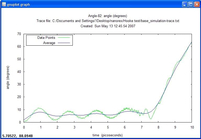
These data points are also available in a text file, but there doesn't seem to be a way to export them to another application like Excel. I am ball-parking the average angle of deflection to be seven degrees, or 2.3 A. This gives a spring constant for the tube of 4.3 N/m.
A cursory search for similar experiments has not turned up anything, but I was able to find a company that sells carbon nanotube AFM probes with a spring constant of 2.8 N/m. If I can find a way to get the raw data out of NE1, or ever need to kill a couple hours by typing it into a spreadsheet, I will perform a more rigorous calculation.
I would like to thank Perry for providing the motivation for this post.
movement 114 rendered in nanotech -or- be careful what you wish for
Looks like someone didn't keep their fingers crossed, or maybe the torque and speed of the rotary motor was set too high at 150 nN-nM and 40Ghz. Also I have been thinking about placing the pinion in a bushing to try and hold it straight. Right now I am relying solely on the rotorary jig to position the pinion, and we all saw how well that worked with the first Pascaline attempt.
More to follow.
Friday, May 11, 2007
movement 114 version IV

What happened to version III? It didn't work. For version III, I built some low profile diamondoid teeth, but kept the sulfur atoms on the pinion to drive the rack. They just slipped past again, but it took another 43 hours to find that out. This is version IV. I doubled the height of the rack teeth and went with a conventional benzene-cnt pinion. Well, we will see how this design works out in a couple days. Keep your fingers crossed for the whole simulation time; I recommend tapping them together which is what I have done. It is likely in the next couple of days you will see scores of people walking around with their fingers tapped together in support, be sure to say hi.*
*I do not believe superstitions are any substitute for good design, but it can't hurt.
Wednesday, May 9, 2007
long simulation of movement 114

Here's the long simulation of movement 114. To put it frankly, the sulfur teeth just don't get any bite on the rack. It is impossible to tell from this straight on view, but there are two rows of sulfur atoms, one on each layer of adamantane. The sulfur atoms on the pinion gear just slip right through. This slippage, and my desire to build a completely diamondoid rack, has made me decide to scrap the sulfur teeth on the rack. I will rebuild them out of adamantane. However at least all the hydrogen atoms are staying put.
Also this piece has 5159 atoms. I set the simulation for 4000 frames with 100 steps per frame. I am simulating it on a Pentium 4, 3.0 GHz, with one-half gig of ram. This simulation took 32 hours and 31 minutes. This is just to give you an idea of how computationally intensive these projects are.
More to follow.
Monday, May 7, 2007
movement 114 rendered in nanotech -or- he huffed and he puffed but couldn't blow this house down
I stayed up to see how the new design worked. I appear to be getting closer. This clip is on the short side, didn't see the need for a really long one if the whole thing broke apart right away. I will make some adjustments where the plates ejected a few atoms and raise the torque on the pinion.
More to follow.
Sunday, May 6, 2007
movement 114 rendered in nanotech -or- she's a brick house

After some helpful advice from Perry Metzger, I present movement 114 version II. It is constructed out of Adamantane, a diamondoid. The rack is two layers thick and the alignment plates are one. The plates are not connected together, but held in place with anchor jigs. If it works with the anchor jigs, I will worry about building a single-piece casing. There are a lot more atoms involved in this version (I forgot to look how many exactly), so it is taking a lot longer to simulate. I will run one overnight, and then we can all watch it fall apart in the morning. <-that sounds rather grim. What I meant to say is I am sure everything will go just fine. However watching stuff break always gives you a good idea of where the weakest link is and just a part of the design process.
Also I am not too sure on the sulfur teeth (I got rid of the nitrogen and oxygen; sulfur has been good to me so far). I might end up having to make the entire rack out of diamondoid and go with a more conventional, and robust, "mutilated pinion".
Saturday, May 5, 2007
movement 114 rendered in nanotech -or- get out of town!
"Uniform circular motion into reciprocating linear motion, by means of a mutilated pinion, which drives alternately top and bottom rack."
Instead of brass I made my rack out of a graphene sheet, carved out to make two rows of linear teeth and end points. I capped the exposed inner carbon atoms with nitrogen. This was inspired by the nitrogen caps I used for the clutch plate on the simple nanotube clutch. For my "mutilated pinion" I inserted a pre-made carbon nanotube from the parts library. I transmuted six carbon atoms from sp2 to sp3 and place one oxygen sp3 atom across each carbon couplet to complete the pinion. To keep the rack aligned I placed four additional graphene plates with multiple anchors around their perimeter.
I guess some more alignment plates are needed? My favorite part is when after the rack flies off, all the hydrogen atoms go flying too; I can almost hear them go "Boing!"
more nanotube clutch and brushing up on my publishing skills
Here are a couple more of the simple nanotube clutch. The only change I made to the clutch system was to extend the secondary shaft. This was to give it more inertia and provide a stable base for the clutch shaft to press up against.
I am also tightening up the look of this place with click-free animation. Over the past couple years I've been collecting "mechanical movements". I have a drawer full of faded yellow reprints, penciled by draftsman who died long before any of us were born, depicting little mechanical systems from Victorian automatons and early industrial infrastructure. These can provide endless inspiration for nano-part design and generally are small enough to simulate on my computer in a reasonable amount of time.
Here you can see there is a lot of slippage between the clutch shaft and the primary shaft. This should not be a big deal. I am confident that I just need to line up the two rows of hydrogen atoms a little better.
Thursday, May 3, 2007
simple nanotube clutch


These are actually animated gifs, but they are not showing up as animated in my browser. I don't know why. If they are not animated in your browser too, and you would like to see them animated I would be happy to send the gif file to you. This is another simple clutch design I have been working on. The movie is pretty short because I can only run the simulation until the clutch shaft (small shaft on the left) actually engages the secondary shaft (small shaft on the right). This limit comes back to not being able to set the travel of the linear motor. Here's another view with the bushing hidden:

In this design I am using nitrogen atoms (blue) to cap the carbon nanotubes. This forms the clutch plate. The primary shaft (largest) has a row of hydrogen atoms around the inside circumference. The clutch shaft also has a row hydrogen atoms on the outside circumference on the end inserted in the primary. My hope is as the clutch slides forward the two rows of hydrogen atoms engage. However I am not sure when I will be able to test the entire system, not until after the linear jig has some more control. Until then I will try to test it out piece wise.
Feel free to contact me for the gif files or for any other reason:
mooreth42@netscape.net
Wednesday, May 2, 2007
nanotube Pascaline - making progress

Between looking around for employment opportunities (ahem ahem) I have had some time to get back to work on my nanotube calculator ambitions. I am still working on developing techniques to build the little systems I know I'll need to build anything resembling a functional computer. The picture is another experiment to demonstrate how to connect three (or more) nanotube shafts of different diameters. This will be extremely valuable for efficiently transferring torques and changing speeds. As usual the small gear is the drive gear, but the heart of the experiment is the thickish looking ring of atoms extending out from the large tube. This is the start of, what I hope will be, a clutch mechanism. The final design should allow me to connect nanotubes of different diameters and start and stop their rotation using a linear motor jig. However, just like with the rotary motor jig, the linear motor jig can not be programmed for a certain amount of travel per direction, at least I don't think it can. I am thinking I may have to add that feature (as I look dishearteningly at the programming textbooks on my shelf). Well, let's just say someone needs to add stepper functionality to the jigs.
But some might ask: "Tom, if this was a real nanotube computer, who would you get to pull the levers to engage it all, Maxwell's demon?"
I bet we would have a good chuckle at their witticism. After everyone had composed themselves I would casually throw out "DNA springs"; game-set-match.
More to follow
Subscribe to:
Posts (Atom)
