Sunday, September 30, 2007

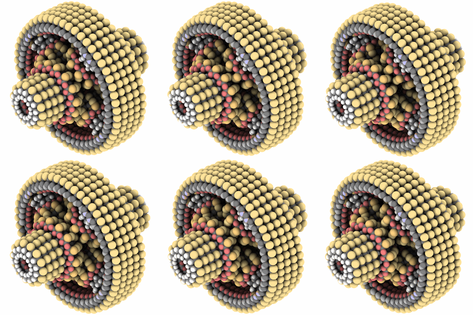
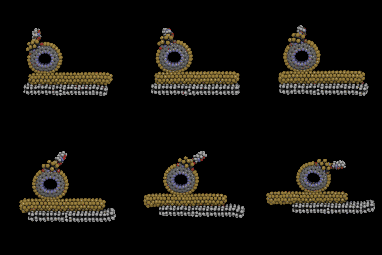
better animation of the lever test


turns out I saved the files at low res...

And just in case: the ring is on a bearing that will ultimately be replaced with a cnt shaft. The big yellow beam is being pushed by a linear motor that will (hopefully) be replaced with some kind of cam.

it's a start


Well after about 30 tries, it is a start. It really did take a lot of iterations to get here. The hardest part was building a beam rigid enough not to bend or collapse. In the end I couldn't build one that didn't bend under the stress of the ring, hence the large SiC slab the beam is resting on. Also, I fluoridated everything; that's why everything has a yellow candy coating. It is a long story, but just think of them as placeholders for hydrogen. I am conducting a couple simultaneous experiments here, probably not the best lab techniques, but what can you do?

Some concerns:
Right now I am not sure how to build robust levers for the thin rings, especially since they are so close together. My lever would have to be one atom thick too? However I can rebuild all the rings similar to the two thick ones on the end, maybe use the original thin rings as spacers.

(I have no idea why this animation looks so pixelated either, but you know, $8, some frosted flakes and all that.)

MTF

Saturday, September 29, 2007

teasing out parts on the motion controller

I have been spending some time taking apart the controller. All I had to start with was a pdb file of the entire part. This means NE1 sees it as a single large cluster of atoms. I need to seperate the components into chunks. I also had to spend a few minutes changing the bond types to graphitic where necessary. I think I will start out with just the main shaft and rings and see if I can get them turning with a regularity.

Here is the main shaft with end caps that sandwiches the rings:

The end rings:


Here is one of the middle rings:

Take a look at the profile on this one:

It has a mono-atomic thickness, not much to hold on to. This is going to be a major aspect of the trickiness. Of course if bad comes to worse, I could build thicker rings and extend the struts and shaft to account for the wider rings. We'll see how it goes.

Friday, September 28, 2007

making a project of Drexler's fine motion controller


Look familiar? It is the Fine Motion Controller for Molecular Assembly designed by K. Eric Drexler and Ralph Merkle. You can read a little description here. The short of the long is it is a device to hold and orientate molecules. The yellow and gray keg-looking thing on top it what it's holding with an arrangement of flaps and fingers. Each finger is connected to one of the blue rings in the middle; turning those moves the struts. I am thinking of trying to do something with this over the next couple of weeks, not rebuild it though. I was reading the linked article when I came across the words "in a complete system..." and went flush. My intent is to add the little levers and cams to make it work and simulate it working. I think it will be tricky, so tricky that I am considering deleting all this right now and just post some more beautiful DNA stuff I've been working on, but the big SME conference is in a couple of weeks, and this just might be the hype they need.

I'm just kidding about the hype stuff. Actually I don't know where devices like this still fit in the roadmap, but it should be a fun challenge anyway.

MTF

the bevel gear posts for Alex

Someone was curious about what the bevel gears in the differential gear box were turning on (see comments-last diff gear post). Here is a picture of the inside of the casing wall showing the posts.

Thursday, September 27, 2007

a historic spool


Yep- another one for the books as the Machine Phase legend keeps growing, not content to ride on past victories, always striving to push the boundaries of what's possible; ladies and gentlemen (probably mostly gentlemen though) I present a tiny spool shaped thing.

Wednesday, September 26, 2007

the differential gear with casing animation


The frames for this one were rendered using a different computer and graphics card. I need to explore what's going on with my graphics card. I got my card for $8 and 4 proofs of purchase from boxes of Frosted Flakes. You?

Tuesday, September 25, 2007

the differential with the casing shown


This is what the gear box looks like with the entire casing made visible. I just hid sections of it for the simulation so I could see the gears turning. Incidentally I also wrote a full tutorial on building this, starting from a single sulfur atom.

Monday, September 24, 2007

a historic differential -or- don't forget the machines


This is the Drexler-Merkle differential gear. It was designed in the mid 90s. I have been told no one was able to simulate it with the casing and bevel posts, until now anyway. The four bevel gears are rotating on little posts bonded to the casing wall. I built it from scratch. I have been trying for the last three weeks or so to get this to work. After a long-ish simulation running over the weekend, I hit pay dirt and there was much rejoicing.

Friday, September 21, 2007

more DNA structures and arrays


The three-point array in CPK veiw

The six star in CPK

A cube. This has been synthesized in the lab.

Carbon nanotubes covalently bonded to the cube. I don't think this has been built yet.

DNA octahedron. This has been synthesized too, link to article abstract.

Full write ups and tutorials on construction in process.

MTF

Thursday, September 20, 2007

a six star DNA array


I am going to try for some 3D structures next.

MTF

Wednesday, September 19, 2007

big DNA post as a make up -or- a three star array

All right I know it isn't an analytical engine, but it's interesting none the less. I have been spending a lot of time catching up on the state of the art in DNA nanotechnology. I have to say I am now a convert. I believe it will be a major enabling technology. Here is a piecewise example. Everything was done in NanoEngineer-1 Alpha 9.

First I inserted two DNA duplexes with 30 base pairs each. Here I am using the reduced PAM-5 model to represent them, but these are more or less the same things you have in your cells.


I positioned them over each other and lined up some phosphate groups on the back bone (displayed in purple).

Next I selected four phosphate groups and made what's called a cross over. You can do this manually or with just a click:

This is not just a trick of the software. There is a well established "wet" process to do this in the lab, or maybe kitchen depending on how you roll. Now the strands have been connected. Here is a color coded picture to show the new connections:

This arrangement is referred to as a Double Anti-Parallel Even Crossover (DAEX). This is the starting point for a lot of larger DNA motifs. Enzymes can be used to create sticky ends and bond the strands together. By dropping in a few more of these, a little arranging and bonding, and you can start to build up arrays like this:

Here I have changed the colors and display mode a little, but you can still make out the different chains.

This array has been synthesized in the lab. What is great about DNA is you can arrange a lot of atoms precisely and quickly. These arrays have been proposed as scaffolding for more complicated structures. Maybe something like this could happen (now I think I am getting speculative).

Here I have attached a thymine molecule to a cnt, just as a quick example.

However by creating additional sticky ends or nucleotide overhangs, you can use these arrays to precisely position other molecules. Maybe this specific example would not work, but you can get the just of the idea. That idea being if I drop a bunch of these thymine doped tubes into solution, they would attach themselves at predetermined positions on the array. Actually I think it would take more than the thymine-adenine hydrogen bond, but there are other ways to attach things, and the tube looks too cool to delete.

MTF
Friday, September 14, 2007

might need to extend the gears


I have started to build some casing parts I can throw in to hold the shafts. Here is a close up of the shafts in their bushings. The spacing puts the gear teeth a little farther apart than I had hoped for.

Some interesting ESP images of the cnt data storage system


First I would like to thank Brian Helfrich at Nanorex for producing these images.

EDIT: the second picture shows the actual atoms that were involved in the calculation. And the fluorines are in yellow, not red. The red-looking atoms are carbons being colored by the red haze in front of them. --My fault

Second- we are not entirely sure what is going on because red represents an area of large positive potential, blue negative. The square shows what atoms were included in the calcs. Here the fluorine atoms are being displayed in red and the nitrogen atom in blue. OR maybe that explains why fluorine is so electron-hungry: the large positive potential helps attract electrons from other atoms? Don't worry. There is additional personnel at Nanorex that should be able to explain what's going on, and I will ask him about the second week of next month. (<-Inside joke--brag!)

Also I know not too long ago I made a bold statement of "keep up the pace" in spite of everything else going on. I would like to point out that I also said I was going to make a huge-ass orrery too, and that hasn't happened. In all fairness to me, the orrery was more of a hardware constraint than a time one.

I got a big old test Monday, but I guess I could cancel a couple dates this weekend (models are a dime a dozen right?). We'll see how it goes.

Monday, September 10, 2007

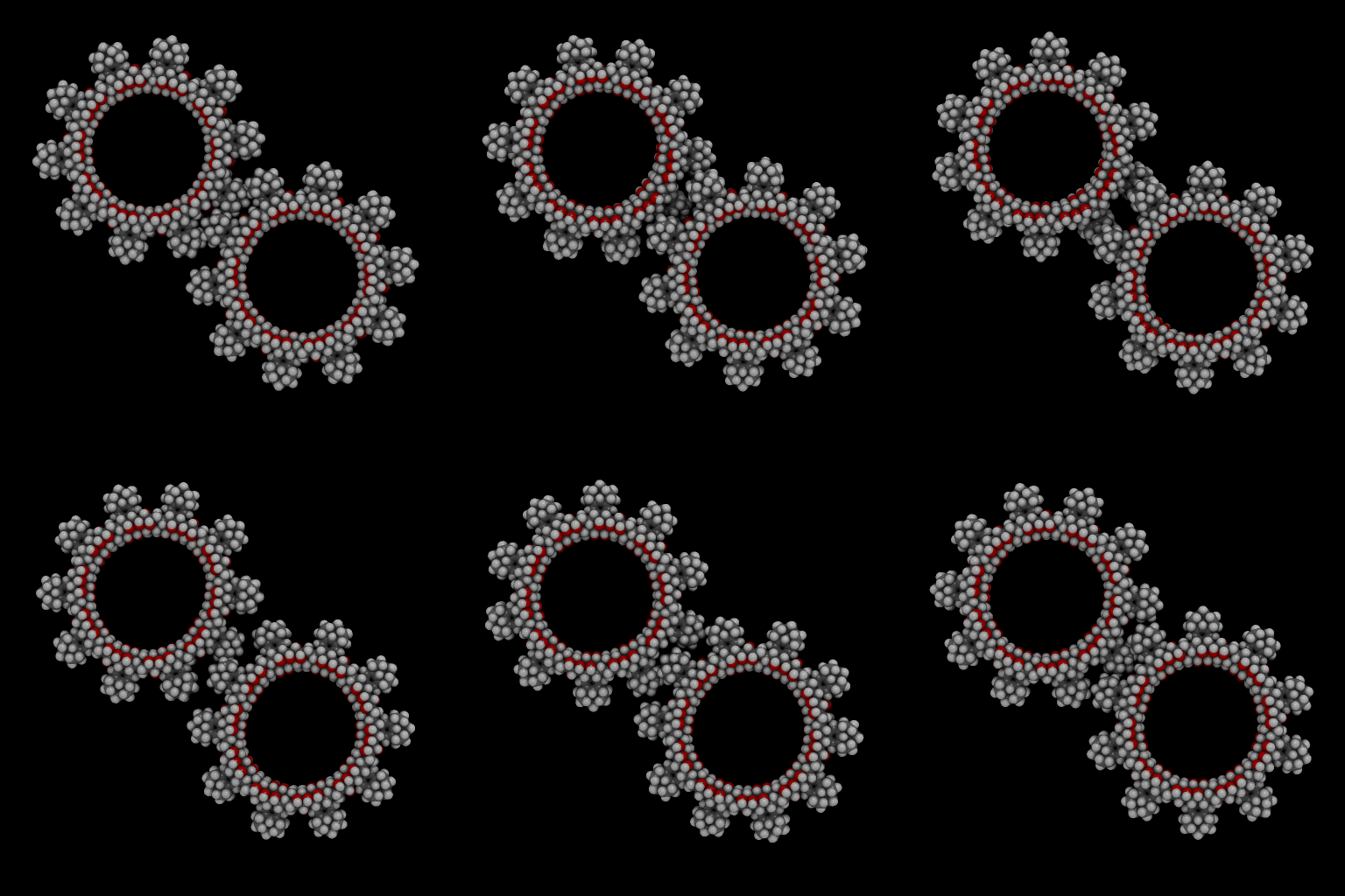
turning the diamondoid 10 gears into shaft


This shaft is the length of five of the single gears, and comes to a just under 4,500 atoms.

Sunday, September 9, 2007

counter rotating diamonoid spur gears


The torque is set to 20nN-nm, and the gears just slip past each other.

Thursday, September 6, 2007

diamondoid spur gears at 90GHz


They could mesh a little better, but making them thicker will probably help that. However they are pretty robust, and the black background really makes them pop. I guess now I'll try to break them.

If I took a little shortcut and used rotary jigs for bearings instead of atomistic shafts, I could build and simulate a system using around a hundred or so of these gears with my two main computers. It would take a month to simulate one iteration, but it would be worth it. Adding shafts and casings would really increase the atom count fast. But I have developed some pretty sophisticated hiding techniques, so I could build and insert little chunks at a time. We'll see. I still need to design the thing first.

Wednesday, September 5, 2007

I guess we could go with diamondoid gears


But will they pass the Perry test?

I'm going to simulate these to make sure the teeth stay on, once in a conventional use and then maybe counter-rotating to see just what they will stand.

MTF

Tuesday, September 4, 2007

you know, for pumps...or turbines


Not too much tonight. Perry has brought up some concerns that the silicon capped spur gears may prefer to react with each other than merely rotate. I am not too sure how to check for that, so I have asked for his help. (see comments last post)

In my day job I have been spending a lot of time writing tutorials that show how to build the things you see here and elsewhere. This afternoon I started one for the famous neon pump designed by K. Eric Drexler. Anymore I am getting to a point where I can look at these things and pretty much see how I would go about building them. However, the rotor of the pump, with its threading, threw me for a loop for a good half hour. But as you can see from the above picture, I figured it out. This one is larger than the original, but I am sure the same process can be used to build it. Creating the threads is really pretty easy. It is connecting them to a shaft I am a little worried about still. I'm not going to spoil all my hard tutorial writing by giving it away here though. The funny difference between writing tutorials and blogging about this stuff is I am sure I am expected to proof-read the tutorials.

Also if anyone looks at the archive calender there on the right, they might wonder what was up with April; only six posts? I was finishing grad school then. There is still at least one more piece of paper I want to file away with the others, and class resumes tomorrow. I fully intend to keep up the breakneck pace though. This is, after all, a place for machines.

Monday, September 3, 2007

now those are spur gears


A refinement to the 10-gears for the mechanical calculator

Whenever I think of molecular gears or what have you, these are a lot closer to what I envision then the tiny little sulfur atom teeth on the last iteration. These silicon tipped teeth look damn near industrial: Detroit style nanotech.

tracking down the cnt data storage system designers

I found out who first published on the using fluorine and hydrogen as a potential storage device. It is a little embarrassing because it was right under my nose the whole time. You have to let a guy know about these things sometimes. Here is the original, and I dare say famous, site where it is referenced. The original paper is:

C. W. Bauschlicher and M. Rosi, "Differentiating between hydrogen and fluorine on a diamond surface", Theor. Chem. Acta, volume 96, pages 213-216 (1997).

Now off to track this down...

getting some help on the electrostatic potential images


Remember how I wanted to create an electrostatic potential image of the cnt data storage system, but couldn't figure out how? Well I still can't, but I am getting some help from my new friend/colleague Brian at nanohive. This is a preliminary picture he made. I just wanted to post it.

MTF

Saturday, September 1, 2007

turning the 10 gears into shaft


I may go back and replace white hydrogen squares with red oxygens. I am not sure if I'm going for the checker board look. I may also extend the teeth another lever too.

I can go ahead and make a counter out of these, but I would like to do something a little more.