Saturday, June 30, 2007
ending the night with some science
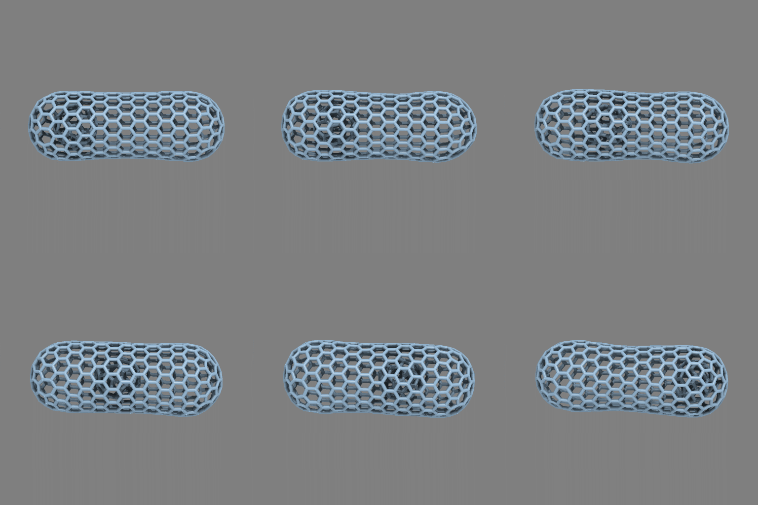
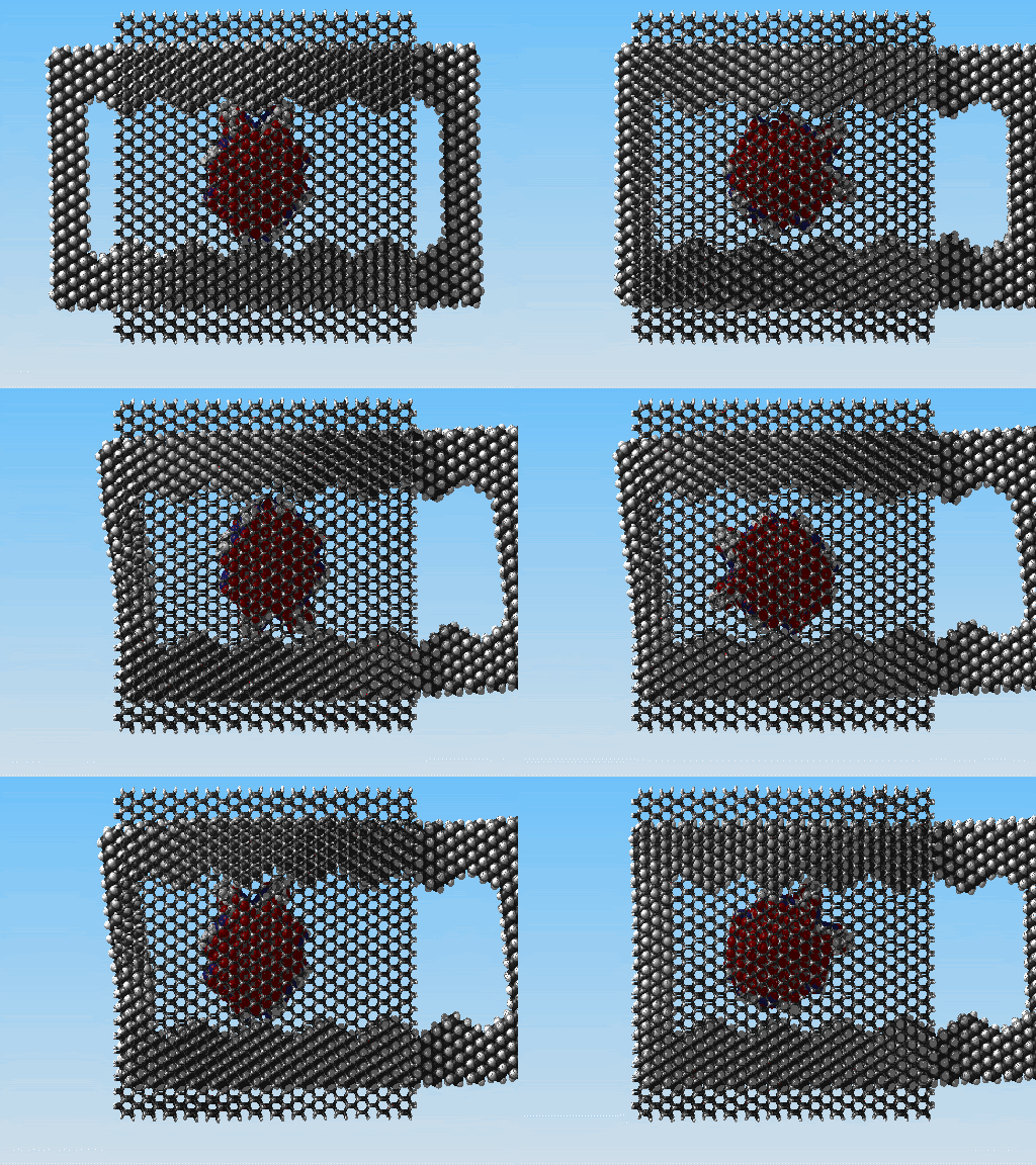
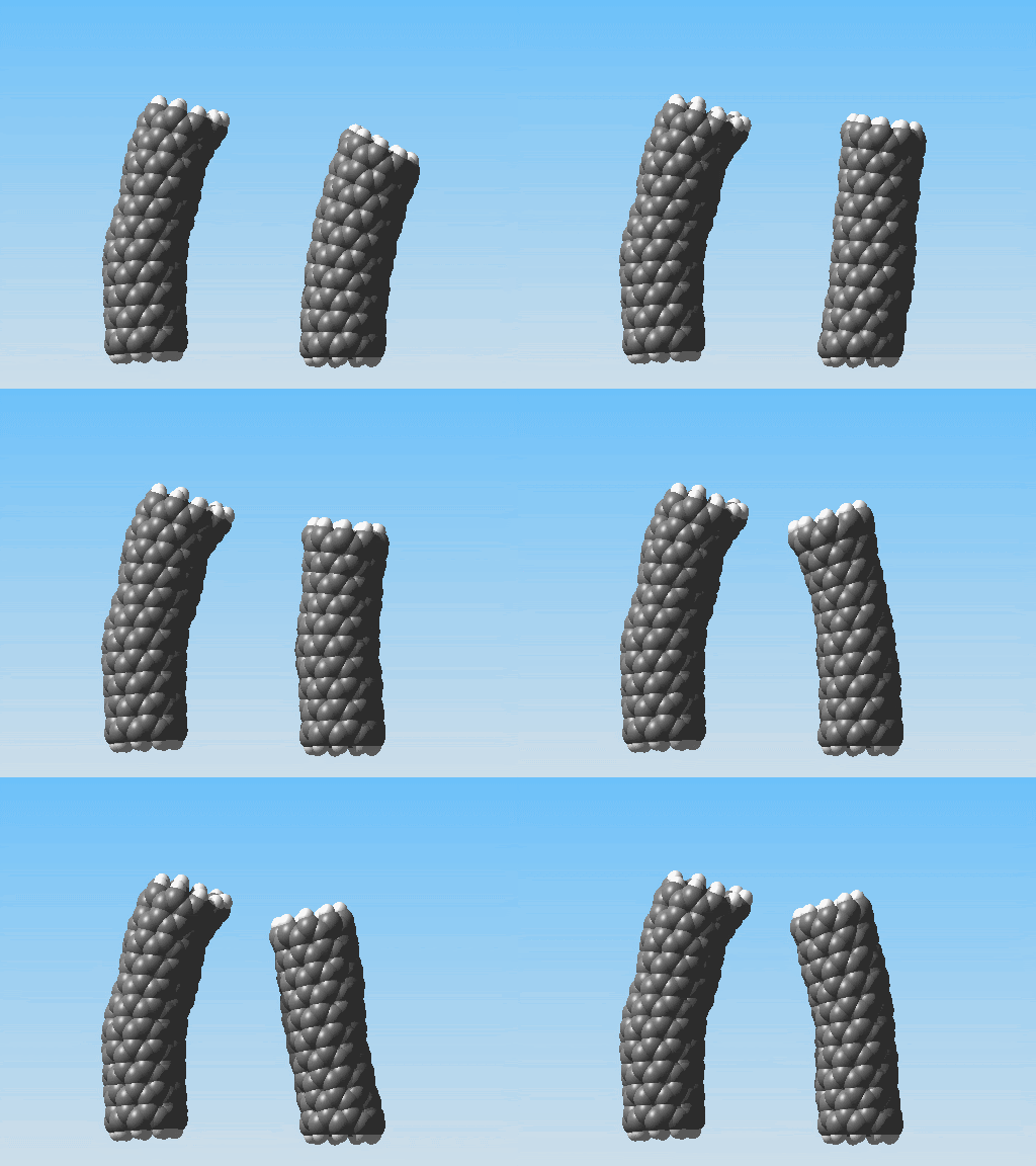
On the right is a carbon nanotube composed entirely of hexagons and was inserted pre-bent at 25 degrees. On the left is a carbon nanotube comprised of pentagon and heptagon defects in the lattice to create a similar bend. Simulating both tubes shows that the tube containing the lattice defects remains rigid while the other tube oscillates.
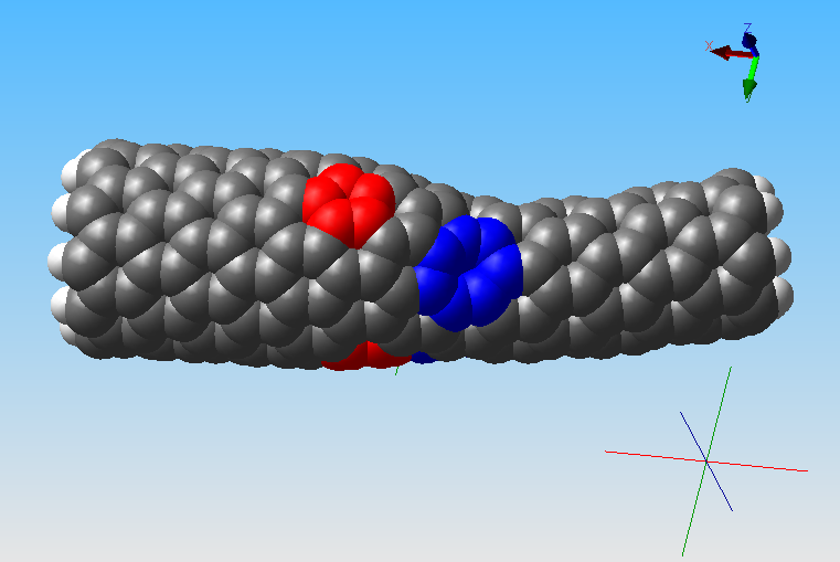
Studying the effects of lattice defects is an important part of nanotube science. I have also been experimenting with using them to create a heterojunction.
Here I have highlighted the lattice defects. The inspiration for this has come from here and David Tomanek's Nano-Velcro.
I'm serious when I say I think this is a real improvement
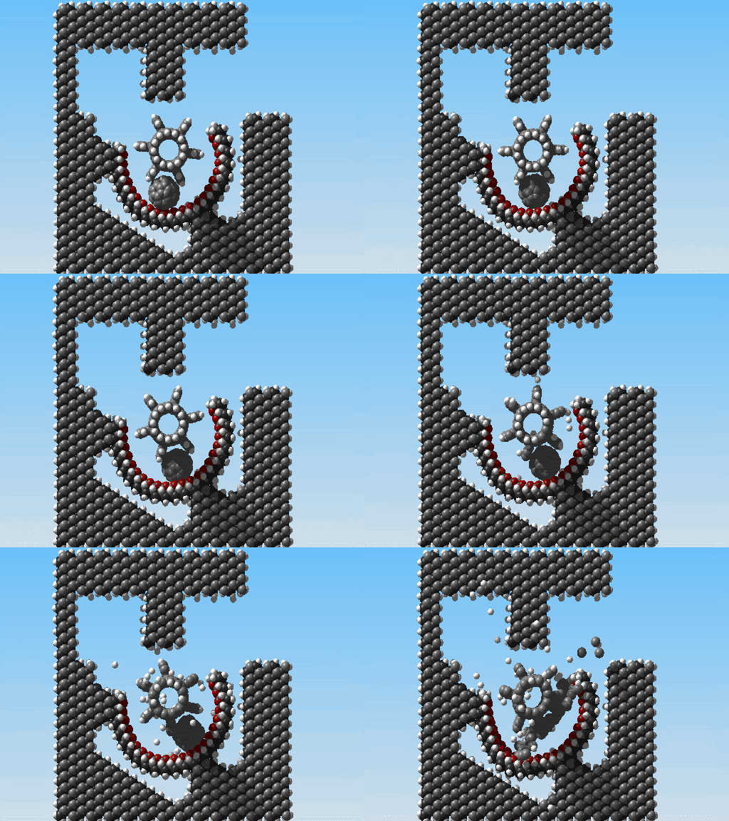
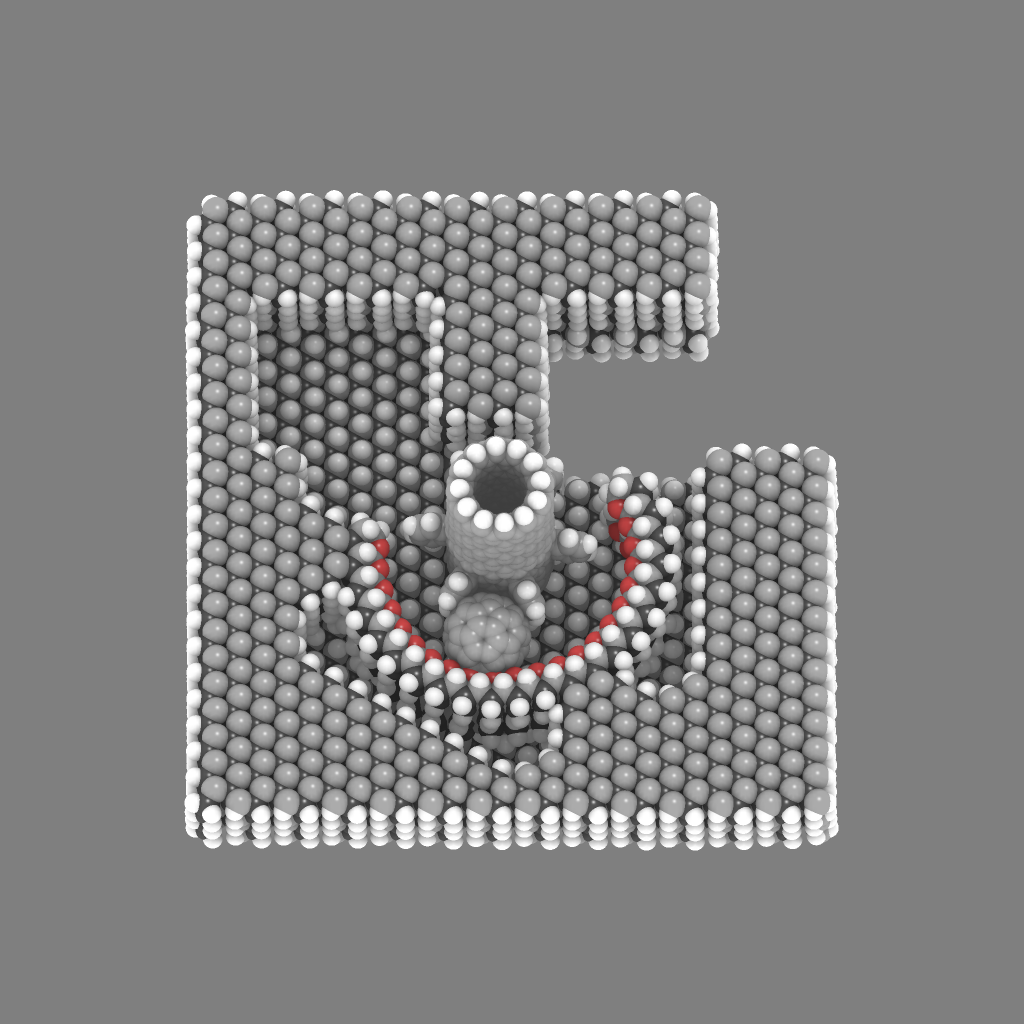
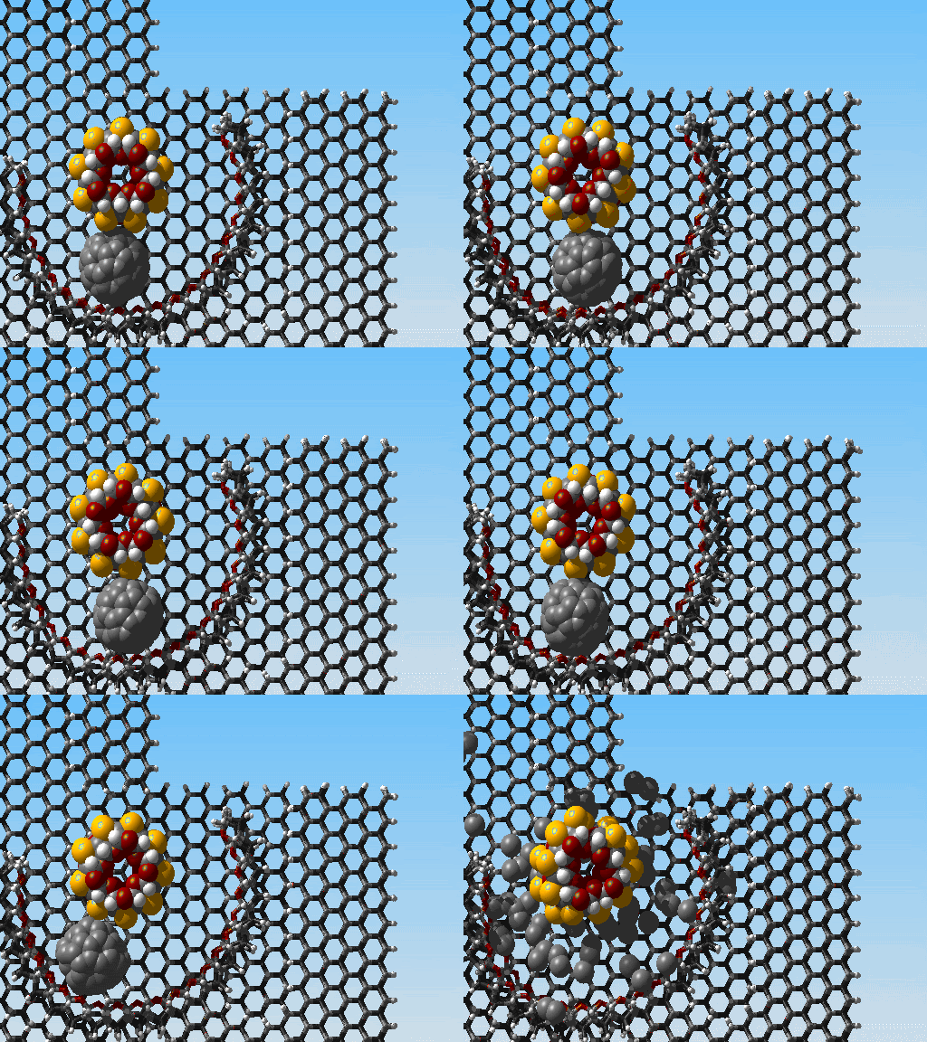
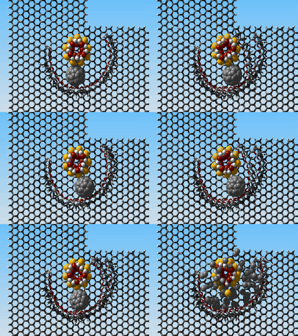
The simulation finished a little later than I thought it would, so that is why I didn't post it last night. You can see that the C60 molecule is well on its way out the hole when a paddle shears against the channel wall; everything kinda of falls apart after that. Next I will make a slight adjustment to the channel wall, decreasing its curvature, and see how it goes.
Perhaps this shearing could have been avoided with a little more due diligence before starting the simulation; the old carpenter's saying of "measure twice, cut once" especially comes to mind. This conjures up images of spinning the paddle in the design console, measuring the distance of closest approach, maybe looking up that value in a table of tolerances I have been keeping during my work, adjusting accordingly, etc. This may, or may not, be a more effective process than the one I currently use which involves rubbing a rabbit's foot across the computer monitor where I think luck is needed*.
*just kidding, the truth is somewhere in between.
Friday, June 29, 2007
simulating a C60 molecule melting
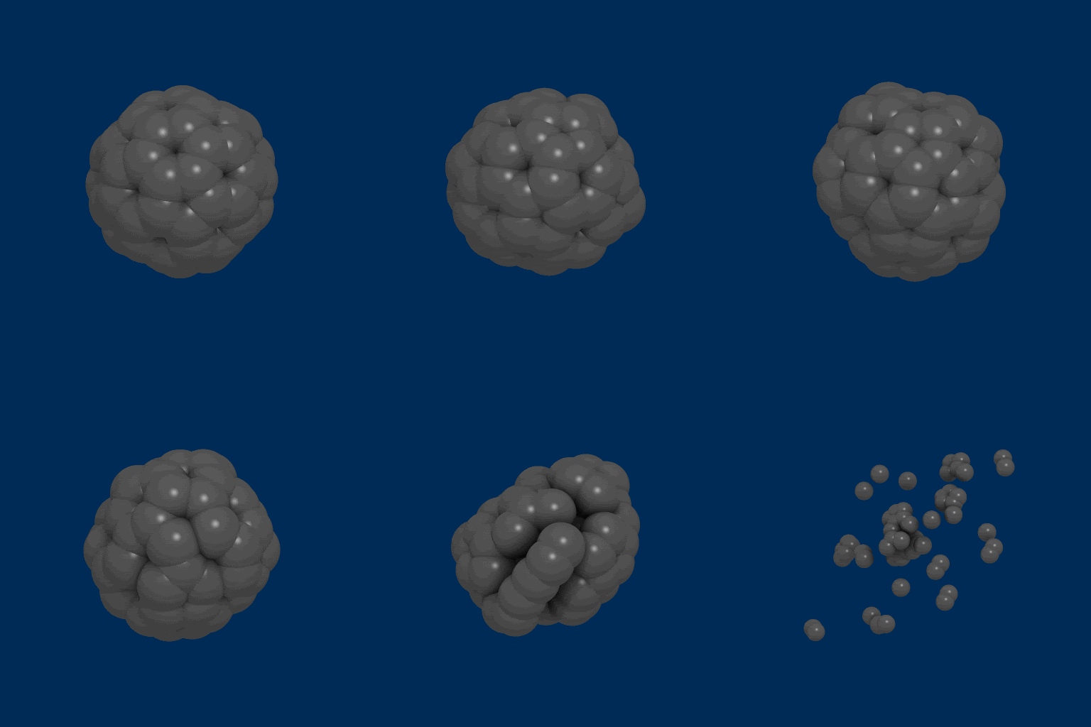
Here is another post inspired by David Tomanek's nanotube page. For this I turned up the heat to 8,500 Kelvin, and the ball comes apart nicely.
The latest simulation of the pump should be finished later on this evening. If it works, or if there is a substantial improvement in its working, I will probably be excited enough to post the simulation tonight. If it bombs, then tomorrow.
MTF.
Wednesday, June 27, 2007
Simulating David Tomanek's carbon nanotube based memory element.
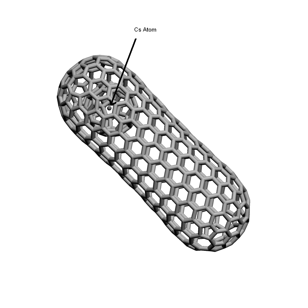
Here is something that might actually be useful and built in the relatively near future. It is a non-volatile memory element that uses the position of a C60 molecule trapped in a carbon nanotube to represent a binary state. You can read a more complete description and see the original simulations done for it here. The buckyball is given a net charge by trapping a cesium atom inside it and then positioned by applying external electric fields.
At first I was a little worried about how I would cap the tubes, but they turned out pretty good.
I was even able to insert an atom inside the buckyball. The atom is not cesium, but plays the role well.
Tuesday, June 26, 2007
cnt based C60 pump update
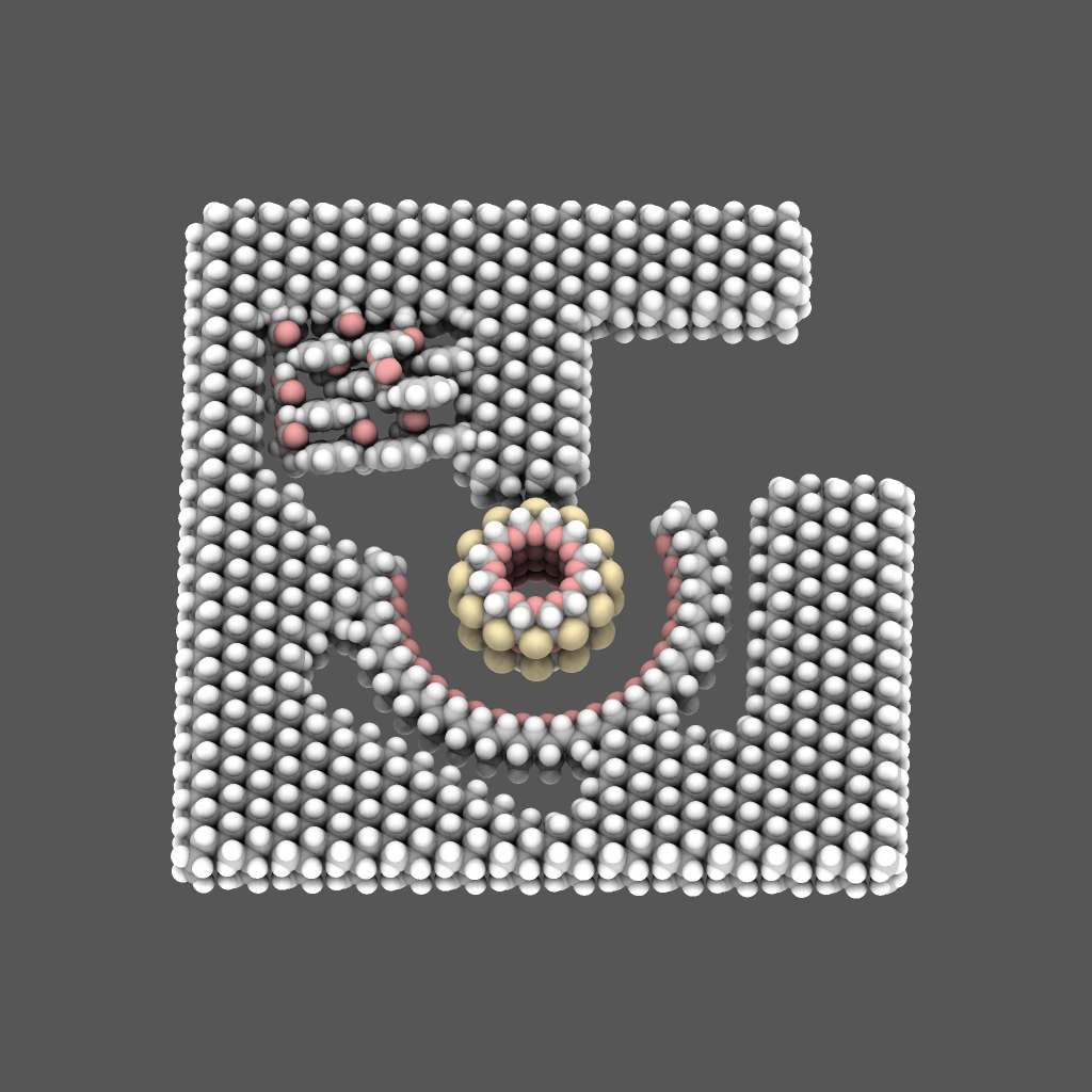
I've started the simulation for the cnt based design. Here is a view looking into the outlet of the pump. The astute observer will notice that the outlet will need to be enlarged in order for a C60 molecule to fit through, but that would be the type of problem I would kill for; the hard part is getting the ball to the hole, getting it out? No problem.
Sunday, June 24, 2007
new pump design with cnt shaft
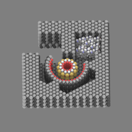
I will try this design next. I will start out will very little torque and speed on the shaft, 10 nN-nM and 10 GHz instead of 60 nN-nN and 60 GHz, and adjust accordingly. This part is still not quite finished yet, I still need to insert the cnt shaft through the casing, but this picture gives you the idea of where I am going. I know it looks like a tight fit for the C60, but there is a slight clearance between it and the benzene paddles. However there is sufficient space to increase the shaft diameter if I need to.
MTF
second C60 pump attempt, it still scatters
I secured the channel side in hope that it was the fluttering that might be transferring some kinetic energy to the bucky ball, but it still breaks up.
Now I am thinking I might ditch the rotor in favor of a paddle wheel design. For this I will cut a hole through the casing and insert a cnt shaft with benzene paddles to push the C60 through.
Saturday, June 23, 2007
first try on a C60 pump
For this simulation all I did was make a slightly smaller rotor and place a C60 molecule in the channel; it's not exactly ready for the pachinko parlors. The remnants of the bushing, that's now serving a part of the flow channel, needs to be secured. However I really don't know what causes the fullerene to start the accelerated spinning that leads to its destruction. I can't see anything from this angle that explains it. Anyone have any thoughts.? Perhaps Damian has this on a feed and can offer an explanation.
Also I haven't stopped working on the orrery, but I must follow where the Muse leads.
Friday, June 22, 2007
yeah right, more like a tryptophan shredder
With the casing hidden things look pretty graphic. I remember back in 57 me and Coger used to run them tryptophans through all sorts of things, pumps, mazes, obstacle courses, debutante balls, whatever it took; I guess they just don't make tryptophan like they used to.
That's ok though, because I didn't really want a tryptophan pump anyway; I have always had my heart set on a C60 pump!
MTF
Friday, June 15, 2007
amino acid pump update and orrery animation
Here is another picture of the tryptophan pump with only the top plate removed. Last night I decided to abort the simulation I had started in favor of a much longer one. I have made that mistake in the past, wasting hours and depositing revenue in the swear-jar as a result.
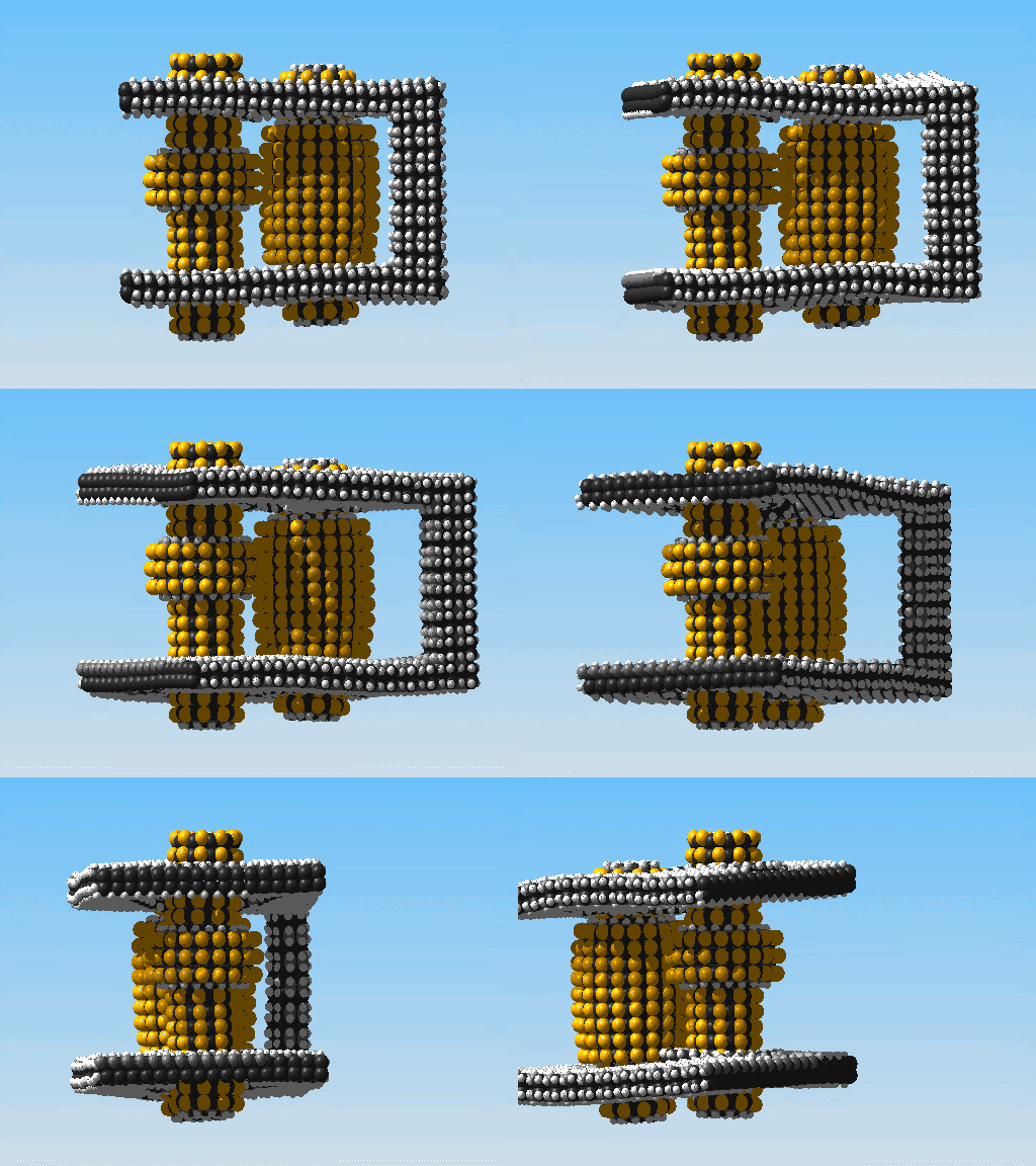
This is the latest version of Ferguson's orrery with the left wall hidden. The B wheel starts to turn in the beginning, but appears to lose too much contact with the A wheel to continue rotating. I placed the B wheel a little closer and simulated it again. When I did, the A wheel started to lose it's integrity. I need to find the sweet spot.
This is the product of three simulation attempts. There are two rotary motors applying torques to the casing. They are situated along the A wheel axis. For the first simulation I had them turning in opposite directions, a buck in the swear jar. For the second attempt I thought I would be clever and attached zero-torque rotors to the B wheel to allow it to rotate freely. However I forgot that these rotors also act as stationary anchors and would not travel with the B wheel on its revolution around the A wheel, in fact they held the B wheel in place, another buck in the jar.
I think the balance of the swear jar is approaching the required funds to pay for some hardware upgrades.
Thursday, June 14, 2007
a neuro-transducer while you're waiting...
I am working on the animations...soon.
But in the mean time I thought we could dream another little dream. This is my first rendition of something that I have been thinking of for a while: the Neuro-Transducer. I dabble in prose science fiction as well as graphic and have used something like this device as a plot point before, mostly for bio-espionage. I imagine clusters of them infiltrating the nervous system of the host and using the protein bundle on the inside of the brackets to identify and adhere to various nerve fibers. Once attached they can either passively pick up the impulses or, perhaps, out-right hijack them. Inter-cluster communication is accomplished through the antenna looking thing on the back. <-I describe it a lot better in the stories.
For now on I am going to use MTF as a shorthand for "more to follow". It will be our little inside code. Cool?
MTF
Wednesday, June 13, 2007
addendum to last post
Just in case there was some confusion on the pump picture, I removed the top and bottom plates so you could see the inner workings. If I simulated it as is, I imagine the tryptophan would just fall out.
sending tryptophan on a little trip
I'll be simulating this overnight. It's a tryptophan pump. There is no special reason why I chose tryptophan, but this may be the start of some kind of filter that would sort out molecules of different sizes. I have no idea how to do it yet, but a sorter that sorted molecules based on chirality would be pretty neat; I understand a Nobel prize in chemistry was awarded for work based on chiral molecules. Regardless, I am going to crank up the torque and see what shakes loose on her. However I am relying solely on the random motion of the tryptophan to cause it to enter the channel; that may be a weak point.
The orrery is coming along. I just wanted to make some minor adjustments and see if anything changed. If all goes well, that simulation should also be done tomorrow too.
As always, more to follow.
Monday, June 11, 2007
a little moonshine never hurt -or- a theoretical design of a DNA delivery bot
This is sort of a Frankenstein's monster, sewn together from the parts of other machines as a favor to a friend. However it was really fun to make, just sort of letting my imagination run a little. The front end bores through the plasma membrane to deliver a couple strands of genetic material. The propulsion system to turbine inspired; anyone that knows me knows I have a thing for turbines. Also it is a LOT easier to make stuff that looks cool than it is to make stuff that works with any semblance of utility. Speaking of which...
The latest simulation of the orrery is done. I will go into the ordeal of why it took so long when I post the animation, but it looks like I might have something I can chalk up in the win column, a small win, but a win none the less.
More to follow.
Thursday, June 7, 2007
I had a pretty great simulation of the latest version of Ferguson's orrery running, but a little problem with the surge protector has set me back a few hours. It's for the best. I am pretty beat; I was up all night last night hustling business plans and Hamiltonians on the corner to raise money for hardware upgrades; I am sure you know the routine: "hey man, this will get you real public" and "Feynman's choice, baby...Feynman's choice". Also the orrery may need to share resources with this:
NanoEngineer-1 just went genetic.
More to follow...
NanoEngineer-1 just went genetic.
More to follow...
Wednesday, June 6, 2007
some more work on Ferguson's orrery
This is an animation of the first A-B wheel simulation. I was not expecting the wheels to lose their integrity the way they did. You can see they initially bow out.
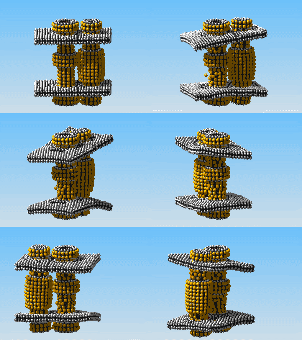
I believe this was because they were placed too close together. Initially I was worried about them being spaced too far apart which lead to the awful looking seam in the casing as I kept removing SiC layers to get them closer.
In the first simulation the point of closest approach is .94A. I decided to rebuild the casing to separate the wheels a little more, to 2.26A.
I also added a full left wall to the casing, and I am working on adding two front struts as well.
This is the new casing with the left wall and one of the front struts. I have also shortened the wheels a little too to make them less flexible.
I am really starting to hit a performance wall with my computer. It takes 15-20 seconds just to bond two atoms together, a step that would be near instantaneous with a low atom-count part. I am not sure if I can finish this project with out first upgrading some hardware.
For about $300 I can buy an ATI X1950 Pro video card and another half gig of ram, or I can put all my hope in an impulsive email sent god only knows where, someplace in the Toshiba Corporation, to god only knows who but definitely someone four or five levels down the hierarchy from someone that can make those decisions.
Hmmmm...
Sunday, June 3, 2007
wrapping up Movement 114, for now anyway
I know I said I was going to make a hi-def animation, but decided not to. The movement starts off great, but then kind of craps out. The pinion just can't push the rack back and slips past instead. I am moving on to Ferguson's orrery, but may revisit Movement 114 in the future. My ability to build different pinions, like a full diamondoid one, is expanding, and perhaps in the future I'll build the kind it would take to make this work.
The full simulation of a 16,000+ atom part at 8000 frames/100 steps took just over 180 hours on an average off the shelf computer.
Friday, June 1, 2007
more on Ferguson's mechanical paradox today
Instead of just chopping a hole through the silicon carbide slab, I backed up a step and inserted some bushings. They might be a tad bit tight, but I ran a quick simulation of the "A-wheel" turning through them and everything held. I also worked on the "thick B-wheel". Next I will add the other two spacer rings on each of the pinions and run another simulation, but not tonight; I need to run out and buy some Visine.
The atom count is over 8,300.
More to follow.
the start of Ferguson's mechanical paradox
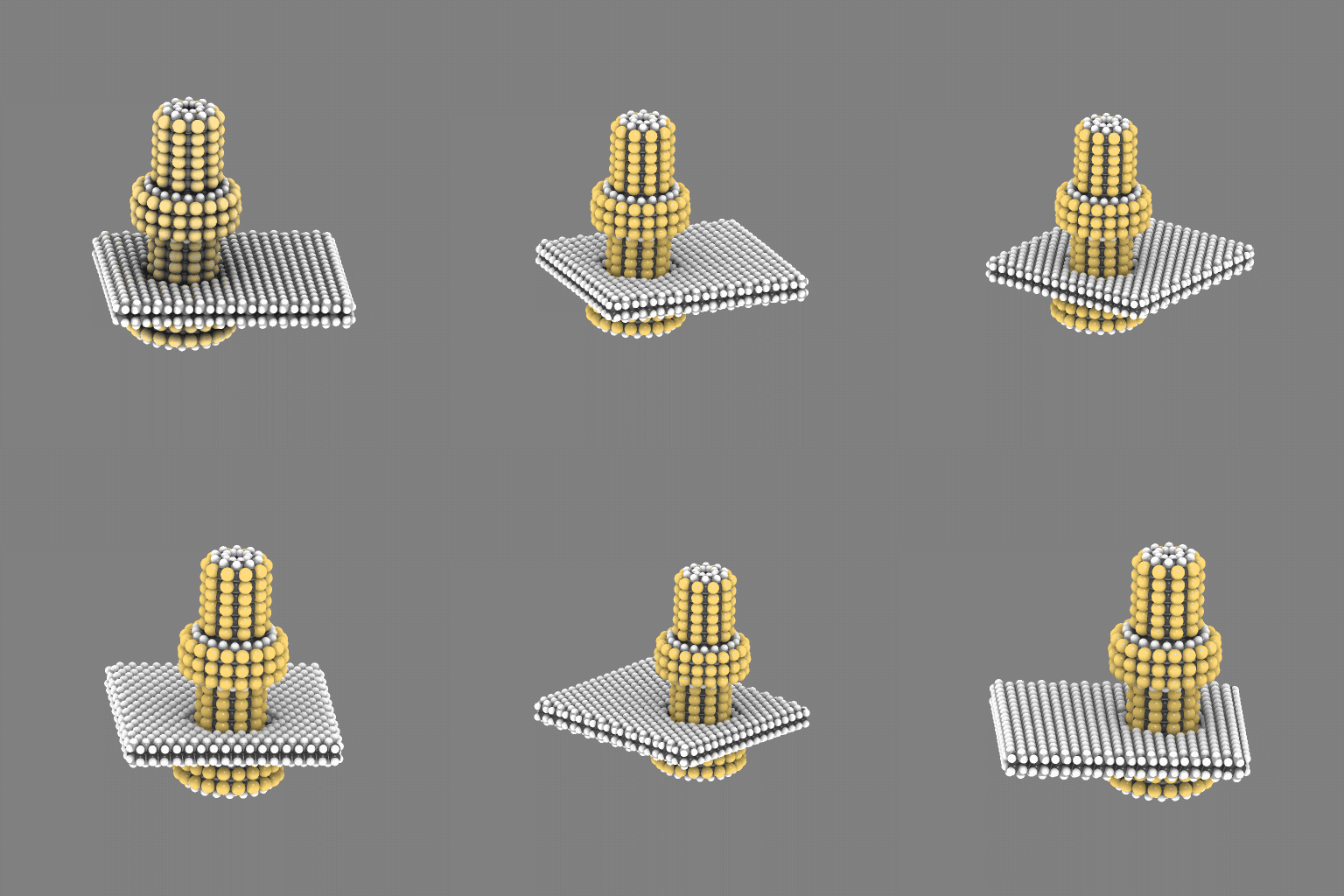
I built this this morning. It is the stationary stud and the fixed "A-wheel" around which the rest of the orrery rotates. Imagine the silicon slab extended outward with a pinion, "M" and "thick wheel B", meshing with the sulfur atoms on this shaft. A little farther out on the slab will be wheels E, F, and G. I am still not sure how I will build three independent gears on the same axis, but I have a can-do attitude. I know I should be thinking really hard about that, but I can't stop the images of a complete orrery with buckyball planets from flashing through my mind.
The atom count has already exceeded 3,500.
Subscribe to:
Posts (Atom)